


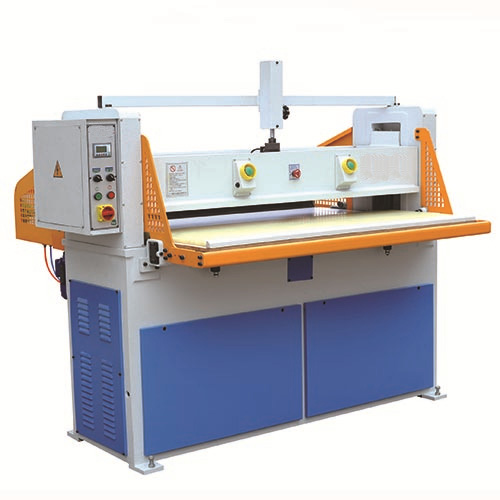
The hydraulic cutting machine is composed of the following three basic parts.
1. Mechanical part: composed of the body, working mechanism and travel adjustment device, gantry hydraulic cutting machine also includes saddle moving feed device and automatic feeding device.
2. Hydraulic system: composed of hydraulic pump, executive element (hydraulic cylinder), control element (pressure valve, directional valve), auxiliary parts (filter, oil tank, pressure gauge, etc.).
3. Control part: including the electrical control circuit composed of components such as switches, relays and contactors, and some photoelectric safety protection devices installed in the cutting machine.
The stroke control of hydraulic cutting machine includes upper limit position adjustment and lower limit position control. There are several methods for upper limit position adjustment of working mechanism.
1. Adjust the limit switch position using a mechanical-electrical-hydraulic interlock control system. During the 1960s-1970s, many hydraulic cutting machines produced domestically and internationally adopted this method to adjust the upper limit position of their working mechanisms. Some new cantilever-type hydraulic cutting machines still employ the traditional electromechanical-hydraulic interlock control method used in conventional hydraulic systems, such as models like SCBON’s 8LE, 8LES, 8LEST, and 8LEST series from Germany, though they utilize contactless switches instead.
2. Electric: The motor drives the power shaft pressure plate to be adjusted through the mechanical transmission mechanism, such as the Czech 06135/P1 hydraulic cutting machine with hydraulic swing arm device.
3. Manual: Turn the handwheel, and directly drive the vertical shaft press plate adjustment through the screw movement of the screw rod, such as the British GSB-I type hydraulic cutting machine.
4. Hydraulic: Turn the handwheel and adjust automatically through the hydraulic follower system, such as the Italian S series model of hydraulic cutting machine.
There are two methods to control the lower limit position of the working mechanism of hydraulic cutting machine.
1. Limit switch control: The position of the limit switch is changed by mechanical-electrical-hydraulic interlock, and the signal of the lower limit position of the control stroke is given by the contact limit switch or contactless switch.
2. Time control: This control method uses a delay circuit to output the input signal after a certain time, thereby controlling the actuation time of the solenoid valve to achieve stroke control. There are direct triggering signals input from the operating button, and there are also triggering signals input through pressure sensing elements using changes in hydraulic circuit pressure.
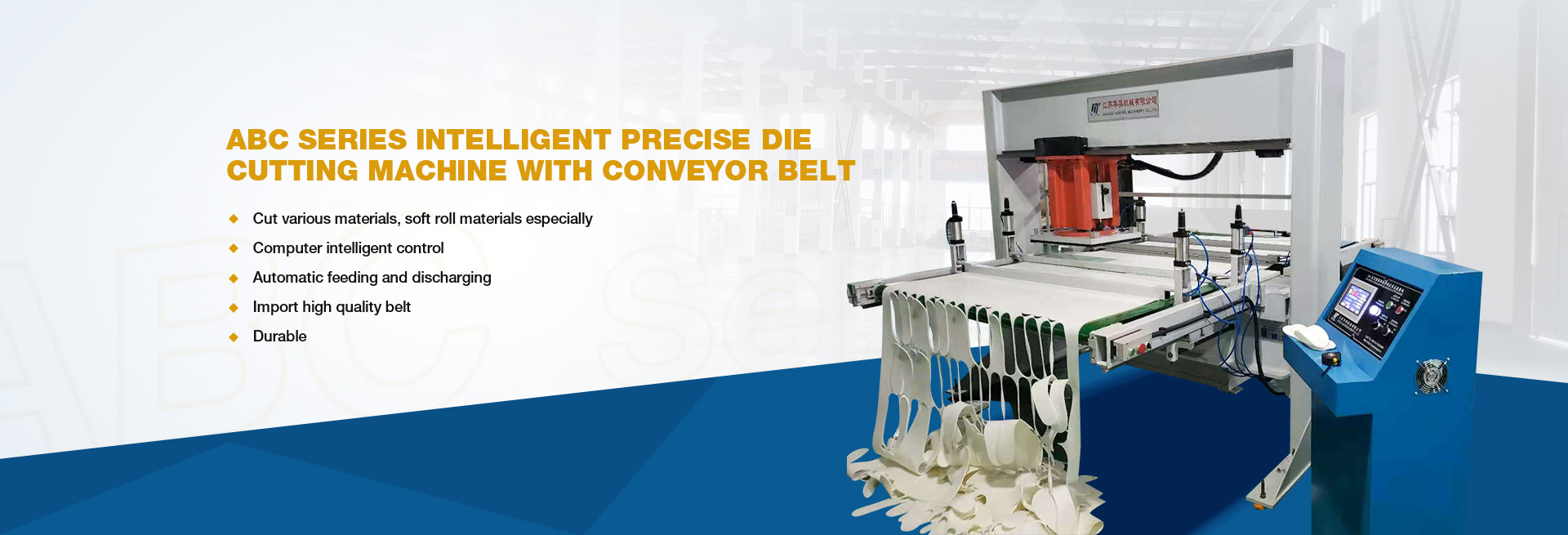
About the use of blade mold in four column cutting press machine
I. The form and cause of tool wear
During metal cutting operations, a four-puller cutting machine experiences simultaneous chip removal and tool wear. Tool failure primarily manifests in two forms: continuous gradual wear (abrasion) and fracture damage (including brittle fractures such as chipping, fragmentation, spalling, and crack propagation) or plastic deformation. This wear reduces machining accuracy, increases surface roughness, intensifies cutting forces, raises temperatures, and may even cause vibrations that disrupt normal operation. Consequently, tool wear directly impacts processing efficiency, product quality, and production costs. The main types of tool wear include:
Front face wear
Wear on the back blade
Border erosion
Regarding temperature dependence, the primary causes of normal tool wear are mechanical wear and thermal/chemical wear. Mechanical wear in four-column cutting systems originates from abrasive particles in workpiece materials, while thermal and chemical wear result from bonding (the interatomic bonding phenomenon between tools and workpiece materials) and diffusion (chemical element exchange between friction surfaces through corrosion).
2. Tool wear process, dulling standard and tool life
As cutting time extends, tool wear intensifies. Experimental data reveals a characteristic wear curve depicting normal wear patterns, with the diagram plotting cutting duration versus backface wear depth (VB) or rake angle groove wear depth (KT). The wear process can be divided into three distinct phases:
Early wear phase
Normal wear phase
Stage of rapid wear
A tool cannot be used after it has worn to a certain limit. This wear limit is called the dulling standard. The actual cutting time of a new tool (or a re-sharpened tool) from the beginning of use until it reaches the dulling standard is called the tool life.
Post time: Oct-12-2025