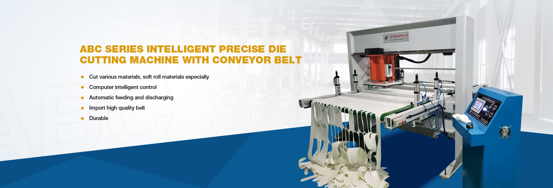
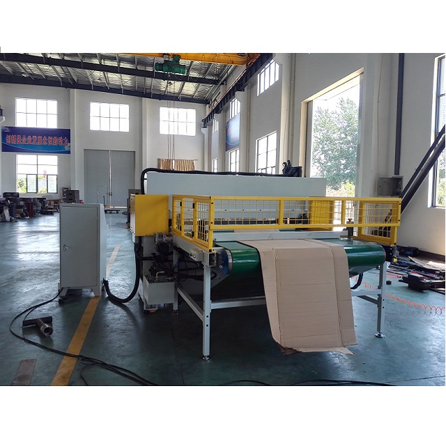
The hydraulic cutting machine employs a variable frequency-driven volumetric throttling speed control circuit. The throttle valve regulates the flow rate entering the working mechanism. To regulate the oil pump’s output flow, a pressure detection transmitter is installed at the throttle valve outlet to control the inverter’s operation, thereby adjusting the AC motor’s rotational speed. By applying variable frequency regulation of the motor speed to control the oil pump’s output flow, the circuit eliminates the need for an overflow valve circuit. Under low-load conditions, the motor operates at high frequency and speed, enabling the oil pump to deliver high-flow output that allows rapid movement of the worktable. During system load operation, the motor runs at low frequency and speed, with the oil pump supplying flow rates matching the working mechanism’s operational speed to ensure stable performance.
When the system’s working pressure exceeds specified thresholds, it ensures operational safety by reducing motor speed to near-zero and oil pump flow to near-zero levels. The system also enables no-load startup capabilities, where the oil pump operates at minimal load without flow output. This effectively eliminates operational instability in hydraulic systems using unloading circuits during transition from unloaded to operational states. The variable frequency hydraulic volumetric throttling speed control system dynamically adjusts pressure according to workload variations, delivering high power efficiency and ideal performance for heavy-duty, high-power applications.
Working Principle of Hydraulic Cutting Machine System When the system is activated, the two-position solenoid valve becomes energized. During no-load operation, the motor operates at high frequency and speed, with the oil pump delivering substantial flow to enable rapid movement of the working mechanism, corresponding to low-load conditions. When the working mechanism engages a load, oil from the pump enters the mechanism through the throttle valve, causing pressure buildup. Upon reaching the preset adjustment value, the pressure transmitter detects this and sends a signal to reduce the variable-frequency motor’s rotational speed. The oil pump then outputs flow matching the throttle valve’s adjusted capacity, maintaining a pressure differential of $p between the valve’s inlet and outlet. According to the throttling speed regulation equation Q=KA$p^{1/2}, the flow rate Q becomes a function of the pressure differential $p. Once the flow cross-sectional area A is set, the pressure differential $p remains constant, ensuring stable flow rate and consequently steady working mechanism speed. In the variable-frequency hydraulic volumetric throttling speed control system, load variations directly affect working pressure. Pressure transmitters detect these changes, triggering adjustments to the motor’s rotational speed to regulate oil pump output flow. This process maintains a nearly constant pressure differential across the throttle valve, thereby stabilizing the working mechanism’s operational speed. For example, when increased load raises working pressure (resulting in higher pressure behind the throttle valve), the pressure transmitter detects this and controls the motor to increase rotation speed. The resulting flow rate boost elevates the pressure before the throttle valve, ultimately keeping the pressure differential within a stable range. When the workload decreases, the working pressure drops, causing a reduction in pressure downstream of the throttle valve. The pressure transmitter detects this change and triggers the variable frequency motor to reduce its rotational speed, thereby decreasing the oil pump’s output flow. As the upstream pressure at the throttle valve decreases, it maintains the original differential pressure $p between the valve’s upstream and downstream sides. By keeping this pressure differential $p constant, the throttling valve maintains stable flow rate through the system, ensuring consistent operation of the working mechanism.
In the system, a quantitative pump is adopted. The cutting machine realizes a new hydraulic volume throttling speed control circuit by changing the motor speed. It is a practical attempt. Compared with the traditional hydraulic speed control method, the variable frequency hydraulic volume throttling speed control circuit has the following advantages:
① The application and speed range of hydraulic volume throttle speed control circuit are expanded;
② No overflow loss, reduce the power loss of the system, through the system efficiency;
③ The quantitative pump is generally simple in structure, low in price, easy to maintain, and not too high in the requirements of the oil medium;
④ When the oil pump is running at high speed, it is in low pressure working state, and when the oil pump is running at low speed, the wear of the oil pump parts and mating pairs is reduced, so the reliability and service life of the hydraulic system are improved.
In practical applications, cutting machines often experience wear, corrosion, fatigue, deformation, and aging of components. These issues can lead to reduced precision, diminished performance, and compromised product quality, with severe cases causing equipment downtime. Hydraulic cutting machine maintenance involves technical interventions such as regular upkeep and repairs to mitigate deterioration, extend operational lifespan, and restore or maintain the machine’s specified functions.
The operation of cutting machine maintenance includes equipment inspection, adjustment, lubrication, immediate handling and reporting of abnormal phenomena. In order to ensure normal operation, reduce wear and tear, protect accuracy and prolong application life, scientific lubrication, maintenance and maintenance are necessary.
I. Inspection of the cutting machine
The inspection of hydraulic cutting machines primarily involves routine checks. Key aspects include equipment vibration, abnormal noises, looseness, temperature rise, pressure, and flow rate. Generally, the machine’s performance and operational status can be assessed through visual observations during operation, basic instruments, and product processing conditions. For instance, this includes monitoring bearing temperature, pressure, speed, punching accuracy, noise levels, as well as hydraulic system oil quality and leaks. In summary, inspection priorities and cycles should be determined based on the machine’s complexity, unique performance characteristics, and importance to product quality, which helps establish repair schedules, timelines, and technical preparations. Routine inspections are typically handled jointly by operators and maintenance personnel.
II. Lubrication of the cutting machine
Lubrication of cutting machines is a crucial measure to reduce wear on components during operation and prevent malfunctions. Poor lubrication of mechanical cutting machine bearings can lead to overheating, seizure, and other issues. Therefore, lubrication management is one of the key aspects of cutting machine maintenance. Implementing the “Five Fixed” method standardizes daily lubrication practices, institutionalizes procedures, streamlines content, and makes them easy to remember.
The specific content is:
1. Fixed point: determine the lubrication parts, lubrication points and inspection points of the equipment.
2. Quality: Use oil according to the oil grade specified in the machine instruction manual.
3. Quantitative: determine the amount of oil added to the lubrication parts of the equipment, avoid waste and rectify oil leakage.
4. Regular: refueling, adding oil and cleaning oil according to the time specified in the machine manual to ensure immediate lubrication.
5. Assign personnel: determine the operators or maintenance workers of lubrication profession, and assign responsibilities to individuals.
From different angles, the hydraulic system of cutting machine can be divided into different forms.
(1) Hydraulic systems can be classified into open and closed systems based on oil circulation methods. In an open system, hydraulic pumps draw oil from a reservoir, which flows through control valves to drive actuators before returning to the reservoir via directional control valves. While this design simplifies structure and facilitates oil cooling and sedimentation, frequent air exposure may cause system instability. Open systems typically feature larger reservoirs and self-priming pumps. Closed systems connect hydraulic pumps directly to actuator return lines, creating sealed circulation paths. Their compact design minimizes air contact, ensuring smoother operation. However, closed systems are more complex due to the absence of reservoirs, resulting in poorer oil cooling and filtration. To compensate for leakage, small-flow make-up pumps and reservoirs are usually required. Additionally, since single-rod double-acting cylinders experience flow imbalance between chambers during operation, power efficiency decreases. Consequently, closed systems generally employ hydraulic motors for actuators.
(2) According to the number of hydraulic pumps in the system, it can be divided into single pump system, double pump system and multi pump system.
(3) Hydraulic systems can be classified into fixed displacement pump systems and variable displacement pump systems based on the type of hydraulic pump used in the cutting machine. Variable displacement pumps offer the advantage of maximizing engine power within their regulation range, though they are characterized by complex structures and manufacturing processes that increase costs. These systems include various configurations such as manual variable, proportional variable, servo variable, pressure-compensated variable, constant-pressure variable, and hydraulic variable types.
(4) Based on the oil supply method to actuating elements, systems can be classified into series and parallel configurations. In a series system, the return fluid from one actuator serves as the inlet for the next, with pressure being reduced at each subsequent element. When the main pump supplies oil to multiple actuators controlled by a directional control valve, achieving coordinated motion across all elements requires sufficient outlet pressure from the hydraulic pump.
The performance requirements for the sealing zone of the cutting machine. This innovation is based on a thorough understanding of the different functions and characteristics of various sections in the sealing device through advanced simulation and analysis methods. Observations across all functional ranges under load revealed that a hydraulic sealing device has a fixed base section subjected to completely different loads, which prevents axial movement of the shaft within the installation space. The material must possess high rigidity, minimal residual deformation, and superior friction properties.
To establish static sealing at the bottom zone and ensure pressure buildup without leakage, the sealing material must demonstrate exceptional elasticity and high clamping force. The sealing ridge area requires dynamic sealing performance under low-temperature conditions while preventing leakage from moving piston rods. This critical section also ensures pressure escalation. The material should exhibit excellent dynamic characteristics, minimal tension-tension ratio at low temperatures, reduced friction, and wear resistance. The gap bridging zone must withstand compression while preventing high-pressure-induced sealing material from being displaced into gaps, demanding materials with high rigidity and hardness.
The hydraulic system of the cutting machine demonstrates no noticeable leakage even during startup at extremely low temperatures. This is because the new hydraulic material does not freeze. Physical freezing in hydraulics refers to the complete hardening of soft components within the material. Remarkably, this hydraulic sealing material maintains high elastic sealing performance at ℃ low temperatures. The polyurethane material retains the same physical properties as standard polyurethane, including hardness and tensile strength. Furthermore, compared to other materials, it exhibits significantly lower friction characteristics. Consequently, using this material can substantially reduce the sliding adhesion effect.
To prevent gap compression and ensure a robust mounting base at the groove bottom, polyurethane material with excellent compressive resistance was employed in the dual-component groove-shaped sealing ring. This design integrates the first material’s superior low-temperature flexibility with the second material’s exceptional compression resistance within a single sealing assembly. The innovation significantly enhances compression safety for hydraulic cylinders with terminal damping, expands operational temperature ranges in extreme cold environments, and improves high-temperature compressive strength. Furthermore, this optimized compression capability allows for greater manufacturing tolerances and wider gap widths while preventing metal slippage.
Post time: Sep-07-2025


